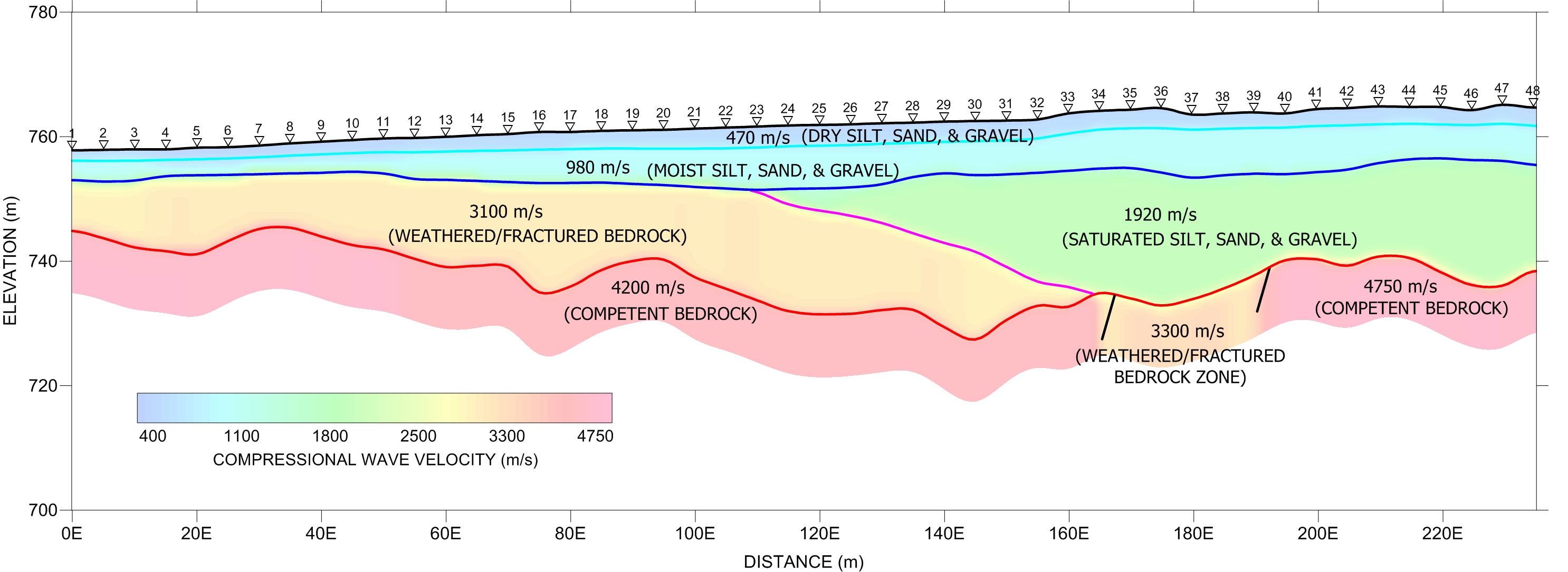
The seismic refraction method, due to its versatility, is one of the most commonly used geophysical methods in engineering, mining, groundwater exploration and environmental site investigations. Based on favourable density contrasts that generally exist between geological materials, the refraction method is utilised to provide detailed information on the distribution and thicknesses of subsurface layers with characteristic seismic velocities. Overburden and basement rocks may be classified to some degree to discriminate for example, glacial tills from gravels or highly fractured rock from competent rock. The technique is widely used for rippability assessment of bedrock.

Field operations involve laying out a seismic cable with several geophone detectors (usually 12 or 24), at the takeout points on the cable. In some situations, such as in saturated sediments, shear wave information is more diagnostic of layer information than compressional wave. In this case a shear wave source and shear wave geophones are employed. Overwater, pressure-sensitive hydrophone receivers are substituted for the geophones. Geophone or hydrophone spacing is strongly dependent on the depth of search and the desired resolution for a given survey. A pattern of shotpoints is then executed within and off the ends of the cable and the seismic wave arrivals for each geophone are recorded in the seismograph. The key piece of recorded information is the time of the first arrival. This arrival is the direct wave, or more commonly, the refracted wave which occurs when seismic energy propagates along a geological interface having a sufficiently great velocity contrast. This contrast must consist of a higher velocity zone underlying a lower velocity zone, fortunately the most common geological condition.
The energy source may be sledge hammer blows in extremely shallow search surveys (less that 10 metres), a shotgun source when overburden conditions allow, or explosives where depth and/or energy attenuation is a deciding factor. The maximum depth of exploration is limited by space requirements for long cable layout and favourable shooting conditions for explosive charges. In general, a seismic cable three times the expected depth of exploration is required to ensure sufficient bedrock or basal layer arrival information to provide depths independently beneath each geophone location.
Interpretation of the seismic data involves resolving the number of velocity layers present, the velocity of each layer, and the traveltime taken to travel from a given refractor up to the ground surface. This time is then multiplied by the velocity of each overburden layer to obtain the thickness of each layer at that point. The analysis of the refraction data is assisted by the use of an integrated suite of programs. As well, inversion programs such as the Optim analysis program are used.
In some circumstances companion surveys may be carried out to provide correlative information. Transient electromagnetic soundings, resistivity soundings, or multielectrode resistivity surveys provide a means of assessing additional layering information. Frequently, the marine seismic refraction method is a companion survey to marine seismic reflection profiling surveys.